Zero Touch Provisioning (ZTP) is a Junos future, very useful when deploying new devices. Basically it allows you to provision all necessary config and software versions with a single cable plug (no extra work needed).
When the new switch arrived all you need to do is take it out of the box power it up and plug it into the network (via management port or any network port).
ZTP was first introduced in Junos 12.2 (know as EZ Touchless Provisioning) since that time it is supporting wider range fo devices including EX , SRX , QFX and more on the roadmap.
I would like to describe a configuration based on Raspberry Pi box as a server. DHCP is used to instruct switch with a details related to config file and install package to fetch. I will use open source software to prepare RPI with needed tools to perform full config and image deployment.
RPI have one ethernet interface and one wi-fi connection. Ethernet is used to setup DHCP interface to propagate settings and wi-fi will be used fo management only (remote access).
nano /etc/network/interfaces
auto wlan0
iface lo inet loopback

auto eth0
allow-hotplug eth0
iface eth0 inet static
  address 10.100.10.1
  netmask 255.255.255.0

allow-hotplug wlan0
iface wlan0 inet dhcp
  wpa-conf /etc/wpa_supplicant/wpa_supplicant.conf

iface default inet dhcp
DHCP sever
DHCP server is responsible for assigning IP addresses to our box (e.g. ex switch). Send instructions regarding config file / software file to upgrade (location of files on ftp server), but also can be used to setup values like hostname, ntp or dns servers.
To install isc-dhcp-server on RPI preinstalled software have to be disabled.
update-rc.d dhcpcd disable
Updating dhcpd.conf
nano /etc/dhcp/dhcpd.conf
# dhcpd.conf
#
# Setting up the options....
#

# option definitions common to all supported networks...
option domain-name "mnsbone.net";
option domain-name-servers ns1.mnsbone.net, ns2.example.org;

option space NEW_OP;
option NEW_OP.image-file-name code 0 = text;
option NEW_OP.config-file-name code 1 = text;
option NEW_OP.image-file-type code 2 = text;
option NEW_OP.transfer-mode code 3 = text;
option NEW_OP.alt-image-file-name code 4= text;
option NEW_OP.http-port code 5= text;
option NEW_OP-encapsulation code 43 = encapsulate NEW_OP;

default-lease-time 60;
max-lease-time 7200;

################################################
### Defining the pool and using the options  ###
################################################


subnet 10.100.10.0 netmask 255.255.255.0 {
  range 10.100.10.10 10.100.10.20;
   option tftp-server-name "10.100.10.1";
   option NEW_OP.transfer-mode "ftp";
   option NEW_OP.image-file-name "/pub/images/ex3400/junos-arm-32-18.2R3-S1.7.tgz";
   option NEW_OP.config-file-name "/pub/config/jn-switch32.config";
}
FTP server setup
nano /etc/vsftpd.conf
listen=YES
#listeni_ipv6=YES


# Allow anonymous FTP? (Disabled by default).
anonymous_enable=YES

anon_root=/var/ftp/
no_anon_password=YES
hide_ids=YES

# Make sure PORT transfer connections originate from port 20 (ftp-data).
#connect_from_port_20=YES
listen_port=21
Change owner for /var/ftp/
chown nobody:nobody /var/ftp/
ZTP in action
After the DHCP and FTP is setup we have to upload config file and image into the ftp folder on the RPI, connect it directly or via switch into MGMT port of the switch and power it on…
Now is the magic happening:
Last login: Thu Jan  1 00:12:28 on ttyu0

--- JUNOS 18.2R3.4 Kernel 32-bit  JNPR-11.0-20190605.30b921f_buil
root@:RE:0% cli
{master:0}
root>
Auto Image Upgrade: DHCP Client Bound interfaces: vme.0

Auto Image Upgrade: DHCP Client Unbound interfaces: irb.0

Auto Image Upgrade: To stop, on CLI apply
"delete chassis auto-image-upgrade"  a

Auto Image Upgrade: DHCP Client Unbound interfaces: irb.0

Auto Image Upgrade: To stop, on CLI apply
"delete chassis auto-image-upgrade"  and commit

Auto Image Upgrade: Active on client interface: vme.0

Auto Image Upgrade: Interface::   "vme"

Auto Image Upgrade: Server::      "10.100.10.1"

Auto Image Upgrade: Image File::  "junos-arm-32-18.2R3-S1.7.tgz"

Auto Image Upgrade: Config File:: "jn-switch35.config"

Auto Image Upgrade: Protocol::    "ftp"


Auto Image Upgrade: FTP timeout set to 7200 seconds


Auto Image Upgrade: Start fetching jn-switch35.config file from server 10.100.1
0.1 through vme using ftp


Auto Image Upgrade: File jn-switch35.config fetched from server 10.100.10.1 thr
ough vme


Auto Image Upgrade: FTP timeout set to 7200 seconds


Auto Image Upgrade: Start fetching junos-arm-32-18.2R3-S1.7.tgz file from serve
r 10.100.10.1 through vme using ftp


Auto Image Upgrade: File junos-arm-32-18.2R3-S1.7.tgz fetched from server 10.10
0.10.1 through vme


Auto Image Upgrade: To install /var/tmp/junos-arm-32-18.2R3-S1.7.tgz image fetc
hed from server 10.100.10.1 through vme


WARNING!!! On successful image installation, system will reboot automatically


Auto Image Upgrade: Installation of /var/tmp/junos-arm-32-18.2R3-S1.7.tgz image
 fetched from server 10.100.10.1 through vme is done, proceeding for reboot of
system


Broadcast Message from root@jn-switch3400
        (no tty) at 0:13 UTC...

Auto image Upgrade: Stopped


*** System shutdown message from root@jn-switch3400 ***

System going down in 1 minute
After this process switch will boot with new software and new config applied.
In case of any problems with image installation, clear switch storage via:
request system storage cleanup
This will free up some space. Then give it a second shoot.
For more advance config option check the juniper docs they are really useful.
Hub and Spoke – multiple CE connected to singe routing instance on PE
I was searching for solution quiet a long time but there is no solution / example in training material or internet. So i decide to solve it by myself.
What do we want to achieves?
As we know the main assumption of L3VPN “Hub and Spoke” is, that the traffic between spokes have to pass via hub. This may be because of a firewall in a main branch or other invigilation purpose ;). I will not talk about hub VRF in this post instead of this i will focus only on the spoke end. There is a case when multiple CE are connected to single PE (e.g. two offices in same city).
Of course we can solve this in very simple way, by creating two routing instance / vrf and connect each CE to each instance. But this is extra config and extra routing instance with in some case can be limited by license.
Our goal in this case is to terminate multiple CEs into a singe vrf, and make sure that the traffic between CEs can’t be exchanged via local routing table. It have to pass via hub even it is directed to CE locally connected to same PE.
Protocols
Full hub and spoke scenario will not be covered here. There is a lot of very good blogs, training materials or other documentation covering this in both with dual and single interfaces from central site to PE with hub and spoke vrf.
I’m using here hub and spoke with two interfaces on hub end (one interface with two vlans). BGP is used to for connection between CE and PE. Hub is receiving all prefixes from spokes and it advertise a default to spokes.
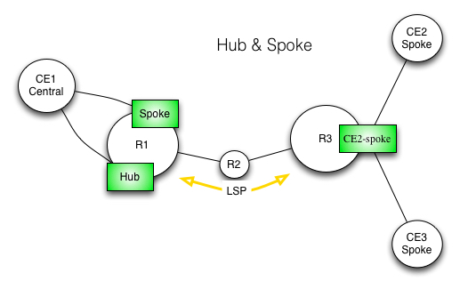
Topology
Topology is very simple.
– Central site CE1 connected by separate interfaces to PE on R1 (Hub / Spoke end).
– Spokes – single PE on R3 with two interfaces and CEs terminates in same routing-instance (CE2-spoke)
L3VPN – Hub and Spoke – Topology
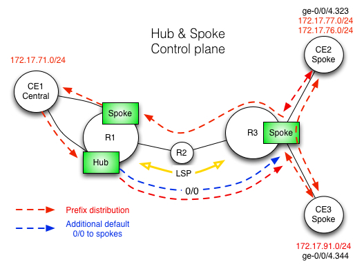
Prefix distribution
Prefix distribution – Control plane
In our scenario EBGP is used between CE2, CE3 and a R3 PE spoke. Same at the hub and spoke end. Prefixes received from CE2 are distributed from R3 spoke routing instance into CE3 and CE1 (as-override is used). We can consider few options here.
We can try to block sending the prefixes from R3 spoke into the CE2 and CE3 by:
– removing as-override
– adding export policy to EBGP
– configuring IBGP
– use static routs etc…
Unfortunately this will not be a solution in this case. No metre with protocol or static will we use forwarding plain always have a next hop pointing to local interface. At the end packet will follow shortest way to the prefix with is local entry in forwarding table (in this case CE2-spoke vrf table on R3). Conclusion is simple we have to get rid of them, and leave only default pointing to hub.
The only solution i can see here is to filter our forwarding plane. After applying filters, we should only have a default 0/0 pointing to hub (CE1) and interface prefixes to both CE2 and CE3. OK, but how will the return traffic sourced from CE2 passing by CE1 hub with a destination of CE3 knows where to forward packets, after reaching our vrf on R3, if we only have an interface routes and 0/0 with direction to CE1?
Since we are not using vrf-table-label (for extra lookup after the mpls header is take off) after striping out VPN label packet is forwarder directly into interface next hop. Here is the explanation founded in juniper training materials:
“The default behaviour of Junos device is to allocate labels on a per next hop basis. A single vrf may have multiple attached CEs. VPN labels are allocated (and advertised by MP-BGP) for each CE-learned VPN route by the PE router based on the PE router’s determination of the best next hop to reach the destination.
When the VPN packet arrivers on agrees PE they are encapsulated in single MPLS label (the VPN label). The forwarding procedure, in the case of per next hop label allocation, is to pop the MPLS label and forward it to the next hop that was learned as described earlier. The IP header is not evaluated for forwarding purposes.”
So the only thing we have to worry about is a local traffic between CE2 and CE3. To limit it we will use the forwarding policy.
Forwarding policy
We are using export policy to allow only 0/0 learned via BGP. We have to apply this on the specific rib group (in this case CE2-spoke.inet.0).
policy-statement def-to-hub-spoke {
 term 1 {
 from {
 route-filter 0.0.0.0/0 exact;
 }
 to rib CE2-spoke.inet.0;
 then accept;
 }
 term 2 {
 to rib CE2-spoke.inet.0;
 then reject;
 }
}

forwarding-table {

    export def-to-hub-spoke;

}
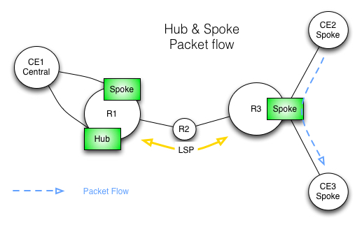
Packet Flow
Default packet flow in L3VPN from CE2 to CE3 – with two CEs connected to same vrf
This is how traffic flows from CE2 to CE3, without any filters applied (directly via R3 spoke rooting instance).
run traceroute source 172.31.77.1 172.31.91.1 routing-instance CE2-5 no-resolve wait 1
traceroute to 172.31.91.1 (172.31.91.1) from 172.31.77.1, 30 hops max, 48 byte packets
 1 192.168.0.89 3.821 ms 1.601 ms 2.567 ms
 2 172.31.91.1 3.527 ms 2.875 ms 2.214 ms
Lets see how is the forwarding table look like without any modifications
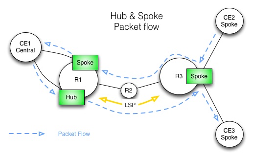
This is how traffic flows from CE2 to CE3 via CE1, with filters on forwarding plain applied.
traceroute source 172.31.77.1 172.31.91.1 routing-instance CE2 no-resolve wait 1
traceroute to 172.31.91.1 (172.31.91.1) from 172.31.77.1, 30 hops max, 48 byte packets
 1 192.168.0.89 10.203 ms 4.787 ms 5.450 ms
 2 172.30.0.81 6.586 ms 5.944 ms 4.080 ms
 MPLS Label=301968 CoS=0 TTL=1 S=0
 MPLS Label=16 CoS=0 TTL=1 S=1
 3 172.30.5.33 7.622 ms 4.562 ms 4.889 ms
 4 192.168.0.42 3.525 ms 4.463 ms 3.889 ms - HUB vrf - CE1
 5 192.168.0.45 6.662 ms 3.824 ms 4.18 ms - Spoke vrf - CE1
 6 172.30.0.29 8.448 ms 6.107 ms 7.234 ms
 MPLS Label=301984 CoS=0 TTL=1 S=0
 MPLS Label=300112 CoS=0 TTL=1 S=1
 7 172.30.0.82 7.215 ms 6.648 ms 8.810 ms
 MPLS Label=300112 CoS=0 TTL=1 S=1
 8 172.31.91.1 11.216 ms 8.072 ms 9.452 ms
This is current routing table for CE2-spoke
show route table CE2-spoke.inet.0

CE2-spoke.inet.0: 13 destinations, 20 routes (13 active, 0 holddown, 0 hidden)
+ = Active Route, - = Last Active, * = Both

0.0.0.0/0 *[BGP/170] 00:06:04, localpref 100, from 172.30.5.41
 AS path: 64600 54591 I, validation-state: unverified
 > to 172.30.0.81 via ge-0/0/0.0, label-switched-path r4-r7
172.30.5.21/32 *[Direct/0] 2d 05:13:00
 > via lo0.1
 [BGP/170] 00:06:04, localpref 100, from 172.30.5.41
 AS path: 64600 54591 I, validation-state: unverified
 > to 172.30.0.81 via ge-0/0/0.0, label-switched-path r4-r7
172.30.5.33/32 *[BGP/170] 00:06:04, localpref 100, from 172.30.5.41
 AS path: I, validation-state: unverified
 > to 172.30.0.81 via ge-0/0/0.0, label-switched-path r4-r7
172.30.5.253/32 *[Direct/0] 2d 05:13:00
 > via lo0.1
 [BGP/170] 00:06:04, localpref 100, from 172.30.5.41
 AS path: I, validation-state: unverified
 > to 172.30.0.81 via ge-0/0/0.0, label-switched-path r3-r1
172.31.71.0/24 *[BGP/170] 00:06:04, localpref 100, from 172.30.5.41
 AS path: 64600 I, validation-state: unverified
 > to 172.30.0.81 via ge-0/0/0.0, label-switched-path r3-r1
172.31.76.0/24 *[BGP/170] 2d 05:12:56, localpref 100
 AS path: 64600 I, validation-state: unverified
 > to 192.168.0.90 via ge-0/0/5.323
 [BGP/170] 00:06:04, localpref 100, from 172.30.5.41
 AS path: 64600 54591 54591 I, validation-state: unverified
 > to 172.30.0.81 via ge-0/0/0.0, label-switched-path r3-r1
172.31.77.0/24 *[BGP/170] 2d 05:12:56, localpref 100
 AS path: 64600 I, validation-state: unverified
 > to 192.168.0.90 via ge-0/0/5.323
 [BGP/170] 00:06:04, localpref 100, from 172.30.5.41
 AS path: 64600 54591 54591 I, validation-state: unverified
 > to 172.30.0.81 via ge-0/0/0.0, label-switched-path r3-r1
172.31.91.0/24 *[BGP/170] 2d 01:37:34, localpref 100
 AS path: 64600 I, validation-state: unverified
 > to 192.168.1.90 via ge-0/0/5.344
 [BGP/170] 00:06:04, localpref 100, from 172.30.5.41
 AS path: 64600 54591 54591 I, validation-state: unverified
 > to 172.30.0.81 via ge-0/0/0.0, label-switched-path r3-r1
192.168.0.40/30 *[BGP/170] 00:06:04, localpref 100, from 172.30.5.41
 AS path: I, validation-state: unverified
 > to 172.30.0.81 via ge-0/0/0.0, label-switched-path r3-r1
192.168.0.88/30 *[Direct/0] 2d 05:13:00
 > via ge-0/0/5.323
 [BGP/170] 00:06:04, localpref 100, from 172.30.5.41
 AS path: 64600 54591 I, validation-state: unverified
 > to 172.30.0.81 via ge-0/0/0.0, label-switched-path r3-r1
192.168.0.89/32 *[Local/0] 2d 05:13:00
 Local via ge-0/0/5.323
192.168.1.88/30 *[Direct/0] 2d 01:38:06
 > via ge-0/0/5.344
 [BGP/170] 00:06:04, localpref 100, from 172.30.5.41
 AS path: 64600 54591 I, validation-state: unverified
 > to 172.30.0.81 via ge-0/0/0.0, label-switched-path r3-r1
192.168.1.89/32 *[Local/0] 2d 01:38:06
 Local via ge-0/0/5.344
Lets see now how does the forwarding looks like with filter applied.
show routing-instances
CE2-spoke {
 instance-type vrf;
 interface ge-0/0/5.323;
 interface ge-0/0/5.344;
 interface lo0.1;
 vrf-import CE2-spoke-import;
 vrf-export CE2-spoke-export;
 protocols {
 bgp {
 group ce {
 type external;
 peer-as 64600;
 as-override;
 neighbor 192.168.0.90;
 neighbor 192.168.1.90;
 }
 }
 }
}
show policy-options
policy-statement CE2-spoke-export {
 term 1 {
 from protocol [ direct bgp ];
 then {
 community add CE2-spoke;
 accept;
 }
 }
}
policy-statement CE2-spoke-import {
 term 2 {
 from {
 protocol bgp;
 community CE2-hub;
 }
 then accept;
 }
}
policy-statement def-to-hub-spoke {
 term 1 {
 from {
 route-filter 0.0.0.0/0 exact;
 }
 to rib CE2-spoke.inet.0;
 then accept;
 }
 term 2 {
 to rib CE2-spoke.inet.0;
 then reject;
 }
}
}
community CE2-hub members target:54591:200;
community CE2-spoke members target:54591:201;
policy-options {
policy-statement CE1-import {
    term 1 {
        from {
            protocol bgp;
            community CE1;
        }
        then accept;
    }
}
policy-statement CE2-hub-export {
    term 1 {
        from protocol [ direct bgp ];
        then {
            community add CE2-hub;
            accept;
        }
    }
}
policy-statement CE2-hub-import {
    term 1 {
        then reject;
    }
}
policy-statement CE2-spoke-export {
    term 1 {
        then reject;
    }
}
policy-statement CE2-spoke-import {
    term 1 {
        from {
            protocol bgp;
            community CE2-spoke;
        }
        then accept;
    }
}
policy-statement default-to-ce {
    term 1 {
        from {
            protocol static;
            route-filter 0.0.0.0/0 exact;
        }
        then accept;
    }
}
community CE2-hub members target:54591:200;
community CE2-spoke members target:54591:201;
}